Extraction Caulking Operation
This equipment has a total of three extraction tanks R101 ~ R103, this section uses R101 as an example to describe the operation of the extraction kettle.
Extractor Pressure Relief Operation
The pressure relief operation of the extraction kettle means that after the extraction of the kettle is completed, the CO2 of the kettle needs to be depressurized until it is emptied.
a) Pressure relief route
Taking extraction kettle R101 as an example, according to the pressure relief route, the extraction pressure relief pressure is divided into
1) Relieve pressure on the separation vessel S201;
2) Relieve pressure on the separation vessel S202;
3) The extraction vessel R102 is discharged to the next preparation;
4) Relieve the pressure in the exhaust gas tank C303 and use the recovery compressor P504 to prepare for recovery;
b) Pressure relief speed
Slowly release the pressure at a rate of about 0.1 bar/s and open the balance valve J26. If the pressure is released too quickly, the following hazards will result:
1) The material is taken out of the material barrel and enters the pipeline, which may clog the valve and contaminate the oil in the separation kettle.
2) It may cause flat deformation of the material bucket, and such failure is not within the scope of warranty;
c) Operation steps
In the actual pressure relief operation, the pressure relief route can be flexibly selected as required. The recommended pressure relief operation flow is (assuming that the current pressure of R101 is 25MPa, the current pressure of the separation vessel S201 is 8MPa, and the current pressure of the separation vessel S202 is 5.5MPa):
1) Close the pressure pump P502/1 or P502/2;
2) Close extraction kettle R101 intake valve J20, open balance valve J26;
3) Set the extraction control valve K01 to the manual mode in the computer, first set the manual opening of the KO1 to 10%. (Observe the pressure relief rate, if the pressure relief rate is slow, the KO1 opening can be adjusted appropriately);
4) As the pressure of the extraction kettle R101 decreases, the pressure release rate slows down, and the KO1 manual opening is appropriately adjusted until the R101 pressure and the separation tank S201 pressure balance (both 8 MPa or so);
5) Set KO1 to automatic mode (because the set pressure is 25MPa, KO1 automatically turns off);
6) Slowly open J36, J59 pressure relief to the separation vessel S202, until the pressure balance, at this time, R101 current pressure is about 5.5MPa;
7) Close J36, J59;
8) If R102 is loaded with materials and ready to work, and R102 inlet and outlet valve is closed, open R101 series valve J33, pressure relief to R102 until the pressure balance, at this time, R102 pressure is about 4 MPa;
9) Close J33, open J36, open KO4 in the computer, press the program to slowly release pressure to the tail gas tank;
10) start the recovery of the compressor P503, R101, C303 C02 recovery to the CO2 storage tank;
11) When R101 pressure is about 0.5MPa, P503 stops automatically. Close K04, J33, slowly open the vent valve J39, empty the remaining CO2 in R101, R101 pressure relief is over.
Take the lid open and close the lid operation
The operation of opening and closing the lid of the extraction kettle refers to the process of opening the kettle cover or closing the lid by using the OP2 console button. There are two automatic operation modes for the lid operation, and R101 is used as an example.
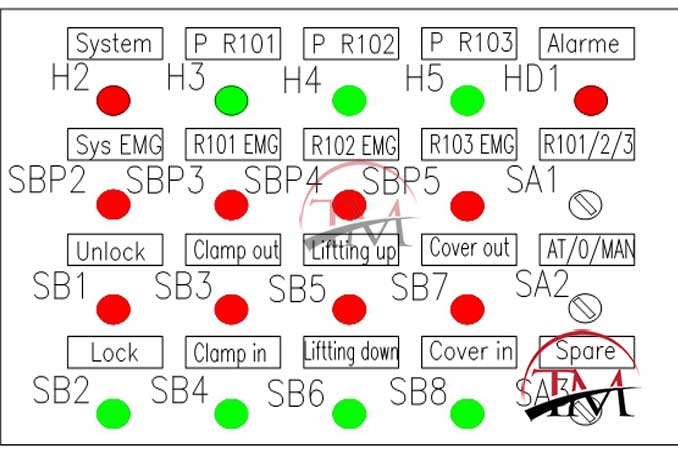
a) Operation button and light function description:
1) H2 (System): system operation indicator, when the PLC system is started and the device is in the running state, the light is on; when the PLC is stopped or the device is in the stop state, the light is off;
2) H3 (P R101): pressure indicator of extraction kettle R101. The light is on when extraction vessel R101 has pressure (more than 0.2 MPa); when lamp R101 has no pressure (less than or equal to 0.2 MPa), the light is off;
3) H4 (P R102): pressure indicator of extraction vessel R102. When the extraction vessel R102 has pressure (more than 0.2 MPa), the light is on; when the extraction vessel R102 has no pressure (less than or equal to 0.2 MPa), the light is off;
4) H5 (P R103): pressure indicator of extraction kettle R103. When the extraction kettle R103 has pressure (more than 0.2 MPa), the light is on; when the extraction kettle R103 has no pressure (less than or equal to 0.2 MPa), the light is off;
5) HD1 (Alarm): Alarm indicator, the light has audible alarm in two cases. The first is when the equipment is in danger or the operator is in misoperation; the other is that after the extraction kettle is closed, it will emit a light alarm for 3 seconds to remind the operation to be completed;
6) SP2 (sys EMG): system emergency stop button, press SP2, PLC stops all devices;
7) SP3 (R101 EMG): R101 stopper emergency stop button, press SP3, PLC stop R101 off cover operation;
8) SP4 (R102 EMG): R102 Caulking emergency stop button, press SP4, PLC stops R102 off cover operation;
9) SP5 (R103 EMG): R103 stopper emergency stop button, press SP5, PLC stop R103 off cover operation;
10) SA1 (R101/2/3): Left, middle, and third gears, the extraction kettle lid switches the switch, left, R101 can perform the kettle lid operation; in the middle, R102 can perform kettle lid operation; to the right, R103 can be performed Capping operation;
11) SB1 (Unlock): Pin cylinder retract button;
12) SB2 (lock): Pin cylinder out button;
13) SB3 (clamp out): clamp open button;
14) SB4 (clamp in): Clamp clamp button;
15) SB5 (Lifting up): Upper cover lift button;
16) SB6 (Lifting down): Upper flat drop button;
17) SB7 (Cover out): button on the top cover;
18) SB8 (Cover in): Upper cover return button;
19) SA2 (AU/0/MAN): Auto/Stop/Manual Switch Button;
20) SA3 (spare): standby conversion button, undefined;
b) Participating equipment:
1) Extraction kettle R101 and related valves;
2) Air compressor P504 and compressed air pipeline;
3) Control system;
c) Operation procedure for manually opening the R101 kettle lid:
1) Observe whether the indicator lamp H3 ((P R101) is off, and confirm that the R101 exhaust valve is in the open state and confirm that there is no pressure in the kettle;
2) Confirm that the air compressor P504 is turned on, if not, operate P504 on the host computer;
3) Rotate SP3 upward (R101 EMG;
4) Rotate SA1 to the left (R101/2/3) with the handle pointing to “R101”; turn SA2 to the right (AU/0/MAN) with the handle pointing to “MAN”;
5) Press the button SB1 → SB3 → SB5 → SB successively to complete the following actions: retract the bolt → expand the clamp → lift the upper flat cover → move the upper flat cover forward. At this point, four steps of opening the cover are completed;
6) Press SP3 (R101 EMG) lock switch cover operation;
d) Operation procedure for automatically opening the R101 kettle lid:
1) Observe whether the indicator lamp H3 ((P R101) is off, and confirm that the R101 exhaust valve is in the open state, confirm that there is no pressure in the kettle;
2) Confirm that the air compressor P504 is turned on, if not, operate P504 on the host computer;
3) Rotate SP3 upward (R101 EMG);
4) Rotate SA1 to the left (R101/2/3) with the handle pointing to “R101”, turning SA2 to the left (AU/0/MAN) and the handle pointing to “AU”;
5) Press SB1, PLC automatically issued instructions to complete: retracting bolt → → clamp expansion → flat cover lift → upper flat cover forward, a total of 4 steps;
6) Press SP3 (R101 EMG) lock switch cover operation;
e) Manually shut down the R101 cover operation process:
1) Confirm that the air compressor P504 is turned on, if not, operate P504 on the host computer;
2) Rotate SP3 upward (R101 EMG);
3) Rotate SA1 to the left (R101/2/3) with the handle pointing to “R101”; turn SA2 to the right (AU/0/MAN) with the handle pointing to “MAN”;
4) Press the button SB8 → SB6 → SB4 → SB2 successively to complete the following actions: the upper flat cover returns, the upper flat cover lowers, the clip clamps, and the bolt protrudes. At this point, the four steps of closing the cover are completed;
5) If the HD1 (Alarm) alarm indicator glows and sounds for 3 seconds, the operation is completed;
6) Press SP3 (R101 EMG) lock switch cover operation;
f) automatically shut down R101 cap operation process:
1) Confirm that the air compressor P504 is turned on, if not, operate P504 on the host computer;
2) Rotate SP3 upward (R101 EMG);
3) Rotate SA1 to the left (R101/2/3) with the handle pointing to “R101”; turn SA2 to the left (AU/0/MAN) with the handle pointing to “AU”;
4) Press the button SB2, the PLC automatically completes the following actions: the upper flat cover returns, the upper flat cover descends, the clip clamps, the bolt extends, and the cover closes in four steps. HD1 (Alarm) alarm indicator light emitting sound alarm for 3 seconds to prompt the completion of the operation;
5) Press the SP3 (R101 EMG) lock switch cover to operate.
Refueling operation of extraction kettle
The refueling operation of the extraction kettle refers to the process of loading and unloading the barrel using an electric hoist. Its operation is as follows:
a) Open the extract kettle top cover according to 4.2.6.2;
b) Operate the electric hoist remote control board and move the electric hoist to the top of the extraction kettle;
c) Lower the hook to the height of the lifting cylinder and hook the barrel handle;
d) Lift the hook slowly, raise the barrel to above the upper plane of the quick-open carriage, move the electric hoist to the side of the platform, place the barrel on the material trolley, shake the handwheel on both sides of the trolley, and lock the barrel;
e) Push the cart to the designated discharge area to discharge.
Tags: herb extraction machine, apex supercritical co2 extractor price, supercritical fluid extraction manufacturers uk, supercritical co2 extraction unit