Extraction Cycling Procedure
Operation steps of one-extractor operation mode (taking R101 as an example)
The specific operations of the extractor R102 and R103 are the same as those of the R101, except that the valves in the operation process of the extractor R101 are different from the valves in the operation process. The specific valve position number refers to the 700L×3 process flow chart. The R101 operation process is as follows:
a) Charge preparation: Put the loaded material barrel (1) into the extractor R101 and close the R101 extractor and quickly open it in place;
b) Close the power supply and start the process water circulation pump P601~P606, start the chiller E407 and heat the boiler E405. After the temperature of the water tank reaches the set value, start the circulating water pumps to cool or heat the cooling and heating system;
c) According to the extraction process parameters set the temperature parameters of each container and heat exchanger and the inlet and outlet pressures of the regulating valves K01, K02, and K03; set the upper pressure limit; under the circumstances the outlet pressure of the pressurized pump is set higher than Extraction working pressure, that is P = Pw +2.0 (Mpa), the maximum can not exceed 35Mpa; lower limit is set to about less than the extraction pressure, that is P = PW-5.0 (MPa);
d) Check whether the quick-opening device of extractor R101 is closed properly, whether the safety pin is locked in place, and confirm that the safety pin is locked in place;
e) After the temperature of each test point reaches the set value, reserve the pressure on extractor R101 (taking P502/1 as an example)
1) According to the R101 work flow chart close the inlet and outlet valves and serial valves J21, J22, J30, J31, J39, and J40 of the extractor R102 and R103;
2) Open valve QF48, QF49, J13, J15, J17, J19, J02A, J20, J23, J35, J26, J38, located at the outlet of CO2 tank C302 to the outlet of R101 extractor, close J32;
3) Set the start frequency of the inverter of the CO2 pressure pump P502/1 to 5~10HZ. Start the pump P502/1. Observe whether the pressure rise of the system is stable when the pump is running, whether the pressure value of the inlet and outlet of the extractor R101 is the same. If there is pressure difference If it is more than 1.5Mpa, it shall be stopped and checked before troubleshooting;
4) When CO2 discharge is observed at the outlets of valves J13, J15, J19, J23, and J35, close the above valves and prepare R101 for pressure;
5) When the pressure of R101 rises to the set pressure, the standby pressure work is completed and the standby pressure of the S201 pipe section can be performed;
f) Reserving pressure of Separator S201 and pipe section
1) In the extractor R101 standby pressure open valve J41, J42, J43, J44, JL01, JL02 between the E403 outlet and the S201 outlet;
2) After R101 is ready for pressure open K01 and inject CO2 into S201;
3) Observe that when J41, J43, and JL02 have CO2 discharge, close valves J41, J43, JL01, and JL02 in order and reserve pressure on S201;
4) When the pressure of S201 rises to the set pressure, the backup pressure is completed;
g) Pressure backup operation of separator S202 and pipe section
1) In the extractor S201 standby pressure open valve J45, J46, J54, JL03, JL04, QF29 between the E403 outlet and the S202 outlet ;
2) After S201 is ready for pressure open K02 and inject CO2 into S202;
3) Observe that when J45, J46, and JL04 have CO2 discharge, close valves J45, J46, JL03, and JL04 one by one, and prepare the pressure for S202;
4) When the pressure of S202 rises to the set pressure, the backup pressure is completed;
h) Pressure backup operation of the circulation loop pipe section (taking S201B as an example)
1) In the extractor S202 standby pressure open valve QF01B, QF03B, J01B, J03B, QF54 between S201B and E401 ;
2) After S202 is ready for pressure open K03 and inject CO2 into S201B and E401;
3) Observe that when J01B and J03B have CO2 discharge, close the valves J01B and J03B in order to complete the backup pressure operation of the cycled pipe section;
i) Perform a cyclic extractor operation
After the system is ready for pressure and the CO2 pressure pump is running for 5 minutes, gradually increase the operating frequency of the CO2 pump: 10HZ→15HZ→20HZ→25HZ→30HZ (Normally the operating frequency of the CO2 pump of the extraction system is 30HZ), and observe the boost pressure at the same time. Whether or not the device is stable, whether the containers, valves, and pipes in the extraction device are leaking or leaking, whether the on-site pressure and the pressure detected by the transmitter agree with each other. If any abnormality occurs, the machine must be shut down immediately for inspection, and the cycled extraction should be continued after the exclusion. The extraction time reaches a predetermined value. After the process, extraction pressure relief can be performed.
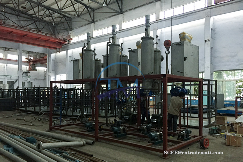
super critical co2 extractor capacity
Tags: hemp complete cbd from co2 extraction 18, super critical co2 extractor capacity, co2 extraction machine homemade, supercritical extra tion cbs austria